10 GHz, 4-FlexChannel, Up to 50 GS/s Mixed Signal Oscilloscope, 62.5 Mpoints Record Length
The Tektronix MSO64B6BW10000 10 GHz, 4-FlexChannel, Up to 50 GS/s Mixed Signal Oscilloscope, 62.5 Mpoints Record Length provides the best signal fidelity for analyzing and debugging today's embedded systems with GHz clock and bus speeds. The remarkably innovative pinch-swipe-zoom touchscreen user interface coupled with the industry's largest high definition display and MSO64B 6-BW-10000 FlexChannel inputs that let users measure one analog or eight digital signals per channel, the MSO64B 6-BW-10000 is ready for today's toughest challenges and tomorrow's too.
The MSO64B 6-BW-10000 offers better visibility into complex systems by offering four, six and eight-channel models with a large 15.6-inch high-definition (1,920 x 1,080) display. Many applications, such as embedded systems, three-phase power electronics, automotive electronics, power supply design, and Power Integrity require the observation of more than four analog signals to verify and characterize device performance and to debug challenging system issues.
Most engineers can recall situations in which they were debugging a particularly difficult problem and wanted greater system visibility and context, but the oscilloscope they were using was limited to two or four analog channels. Using a second oscilloscope involves significant effort to align the trigger points, difficulty in determining the timing relationships across the two displays, and documentation challenges.
Users might assume that a six and eight-channel oscilloscope would cost 50% or 100% more than a four-channel oscilloscope, and will be pleasantly surprised to find that six-channel models are only ~25% more than four channel models and eight-channel models are only ~67% (or less) more than four channel models. The additional analog channels can pay for themselves quickly by enabling users to keep current and future projects on schedule.
The MSO64B 6-BW-10000 redefines what a Mixed Signal Oscilloscope (MSO) should be. FlexChannel technology enables each channel input to be used as a single analog channel, eight digital logic inputs (with the TLP058 logic probe), or simultaneous analog and spectrum views with independent acquisition controls for each domain. Imagine the flexibility and configurability this provides.
Users can change the configuration at any time by simply adding or removing TLP058 logic probes, so that they always have the right number of digital channels.
Previous-generation MSOs required tradeoffs, with digital channels having lower sample rates or shorter record lengths than analog channels. The MSO64B 6-BW-10000 offers a new level of integration of digital channels. Digital channels share the same high sample rate (up to 50 GS/s), and long record length (up to 1 Gpoints) as analog channels.
The stunning 15.6" (396 mm) display in the MSO64B 6-BW-10000 is the largest display in the industry. It is also the highest resolution display, with full HD resolution (1,920 x 1,080), enabling users to see many signals at once with ample room for critical readouts and analysis.
The viewing area is optimized to ensure that the maximum vertical space is available for waveforms. The Results Bar on the right can be hidden, enabling the waveform view to use the full width of the display.
The MSO64B 6-BW-10000 offers a revolutionary new Stacked display mode. Historically, scopes have overlaid all waveforms in the same graticule, forcing difficult tradeoffs:
The new Stacked display eliminates this tradeoff. It automatically adds and removes additional horizontal waveform 'slices' (additional graticules) as waveforms are created and removed. Each slice represents the full ADC range for the waveform. All waveforms are visually separated from each other while still using the full ADC range, enabling maximum visibility and accuracy. And it's all done automatically as waveforms are added or removed. Channels can easily be reordered in stacked display mode by dragging and dropping the channel and waveform badges in the Settings bar at the bottom of the display. Groups of channels can also be overlaid within a slice to simplify visual comparison of signals.
The massive display in the MSO64B 6-BW-10000 also provides plenty of viewing area not only for signals, but also for plots, measurement results tables, bus decode tables and more. Users can easily resize and relocate the various views to suit the application.
The Settings Bar - key parameters and waveform management
Waveform and scope operating parameters are displayed in a series of "badges" in the Settings Bar that runs along the bottom of the display. The Settings Bar provides Immediate access for the most common waveform management tasks. With a single tap, users can:
The Results Bar - analysis and measurements
The Results Bar on the right side of the display includes immediate, onetap access to the most common analytical tools such as cursors, measurements, searches, measurement and bus decode results tables, plots, and callouts.
DVM, measurement and search results badges are displayed in the Results Bar without sacrificing any waveform viewing area. For additional waveform viewing area, the Results Bar can be dismissed and brought back at any time.
Scopes have included touch screens for years, but the touch interface has been an afterthought. The MSO64B 6-BW-10000's 15.6" display includes a capacitive touchscreen and provides the industry's first oscilloscope user interface truly designed for touch.
The touch interactions that people use with phones and tablets, and expect in a touch enabled device, are supported in the MSO64B 6-BW-10000.
Smooth, responsive front panel controls allow users to make adjustments with familiar knobs and buttons, and they can add a mouse or keyboard as a third interaction method.
The MSO64B 6-BW-10000 offers users the choice of whether to include a Microsoft Windows operating system.
The MSO64B 6-BW-10000 comes with a standard removable SSD that contains a closed embedded operating system that will boot as a dedicated scope with no ability to run or install other programs. An optional SSD with Windows 10 operating system is available that will boot to an open Windows 10 configuration, so users can minimize the oscilloscope application and access a Windows desktop where they can install and run additional applications on the oscilloscope, or they can connect additional monitors and extend the desktop. Simply swap the drives as needed through an access panel on the bottom of the instrument.
Whether users run Windows or not, the oscilloscope operates in exactly the same way with the same look and feel and UI interaction.
Need higher channel density?
The 6 Series is also available as a low-profile digitizer - the LPD64. With four SMA input channels plus an auxiliary trigger input, in a 2U high package and 12-bit ADC's, the 6 Series Low Profile Digitizer sets a new standard for performance in applications where extreme channel density is required.
Experience the performance difference
With up to 10 GHz analog bandwidth, 50 GS/s sample rates, standard 62.5 Mpts record length and a 12-bit analog to digital converter (ADC), the MSO64B 6-BW-10000 has the performance users need to capture waveforms with the best possible signal fidelity and resolution for seeing small waveform details.
To debug a design problem, first the user must know it exists. Digital phosphor technology with FastAcq provides users with fast insight into the real operation of the device. Its fast waveform capture rate - greater than 500,000 waveforms per second - gives users a high probability of seeing the infrequent problems common in digital systems: runt pulses, glitches, timing issues, and more. To further enhance the visibility of rarely occurring events, intensity grading indicates how often rare transients are occurring relative to normal signal characteristics.
The MSO64B 6-BW-10000 provides the performance to capture the signals of interest while minimizing the effects of unwanted noise when users need to capture high-amplitude signals while seeing smaller signal details. At the heart of the MSO64B 6-BW-10000 are 12-bit analog-to-digital converters (ADCs) that provide 16 times the vertical resolution of traditional 8-bit ADCs.
A new High Res mode applies a hardware-based unique Finite Impulse Response (FIR) filter based on the selected sample rate. The FIR filter maintains the maximum bandwidth possible for that sample rate while preventing aliasing and removing noise from the oscilloscope amplifiers and ADC above the usable bandwidth for the selected sample rate.
High Res mode always provides at least 12 bits of vertical resolution and extends all the way to 16 bits of vertical resolution at ≤ 625 MS/s sample rates and 200 MHz of bandwidth. The following table shows the number of bits of vertical resolution for each sample rate setting when in High Res.
New lower-noise front end amplifiers further improve the MSO64B 6-BW-10000's ability to resolve fine signal detail.
A new TEK061 front end amplifier sets a new standard for low-noise acquisition providing the best signal fidelity to capture small signals with high resolution.
A key attribute to being able to view fine signal details on small, high-speed signals is noise. The higher a measurement systems' intrinsic noise, the less true signal detail will be visible. This becomes more critical on an oscilloscope when the vertical settings are set to high sensitivity (like ≤ 10mV/div) in order to view small signals that are prevalent in high-speed bus topologies. The MSO64B 6-BW-10000 has a new front-end ASIC, the TEK061, that enables breakthrough noise performance at the highest sensitivity settings. The 'B' version of the MSO64B 6-BW-10000 has a new 50 GS/s low noise interleave sample rate on up to two channels that reduces noise by almost 3 dB at higher volts/div settings, furthering the advantage over competitive scopes in low noise performance. The table below shows a comparison of typical noise performance of the MSO64B 6-BW-10000 and prior generations of Tektronix oscilloscopes in this bandwidth range.
Discovering a device fault is only the first step. Next, users must capture the event of interest to identify root cause. The MSO64B 6-BW-10000 provides a complete set of advanced triggers, including:
With up to a 1 Gpoint record length, users can capture many events of interest, even thousands of serial packets in a single acquisition, providing high-resolution to zoom in on fine signal details and record reliable measurements.
Finding the right cycle of a complex bus can require hours of collecting and sorting through thousands of acquisitions for an event of interest. Defining a trigger that isolates the desired event speeds up debug and analysis efforts.
Visual Trigger extends the MSO64B 6-BW-10000's triggering capabilities by scanning through all waveform acquisitions and comparing them to onscreen areas (geometric shapes). An unlimited number of areas can be created using a mouse or touchscreen, and a variety of shapes (triangles, rectangles, hexagons, or trapezoids) can be used to specify the desired trigger behavior. Once shapes are created, they can be edited interactively to create custom shapes and ideal trigger conditions.
By triggering only on the most important signal events, Visual Trigger can save hours of capturing and manually searching through acquisitions. In seconds or minutes, users can find the critical events and complete the debug and analysis efforts. Visual Trigger even works across multiple channels, extending its usefulness to complex system troubleshooting and debug tasks.
Once multiple areas are defined, a Boolean logic equation can be used to set complex trigger conditions using on-screen editing features.

Reference: ME19650199MM
Brand: Megger
2.5 kV High Voltage Hand-Held Insulation and Continuity Tester
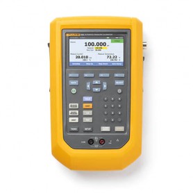
Reference: AM40919658AA
Brand: Amprobe
1000V/1000A TRMS AC/DC Navigator Clamp Meter w/ Temperature. THD and NCV Detector
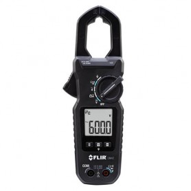
Reference: FL63088405FC
Brand: Flir
600V/400A,True-RMS AC Digital Clamp Meter, with NIST Calibration
10 GHz, 4-FlexChannel, Up to 50 GS/s Mixed Signal Oscilloscope, 62.5 Mpoints Record Length